Baker Hughes · JewelSuite Well Engineering
Complex tool integration
Helping to integrate a legacy engineering tool and making it intuitive, faster, and easier to interpret.
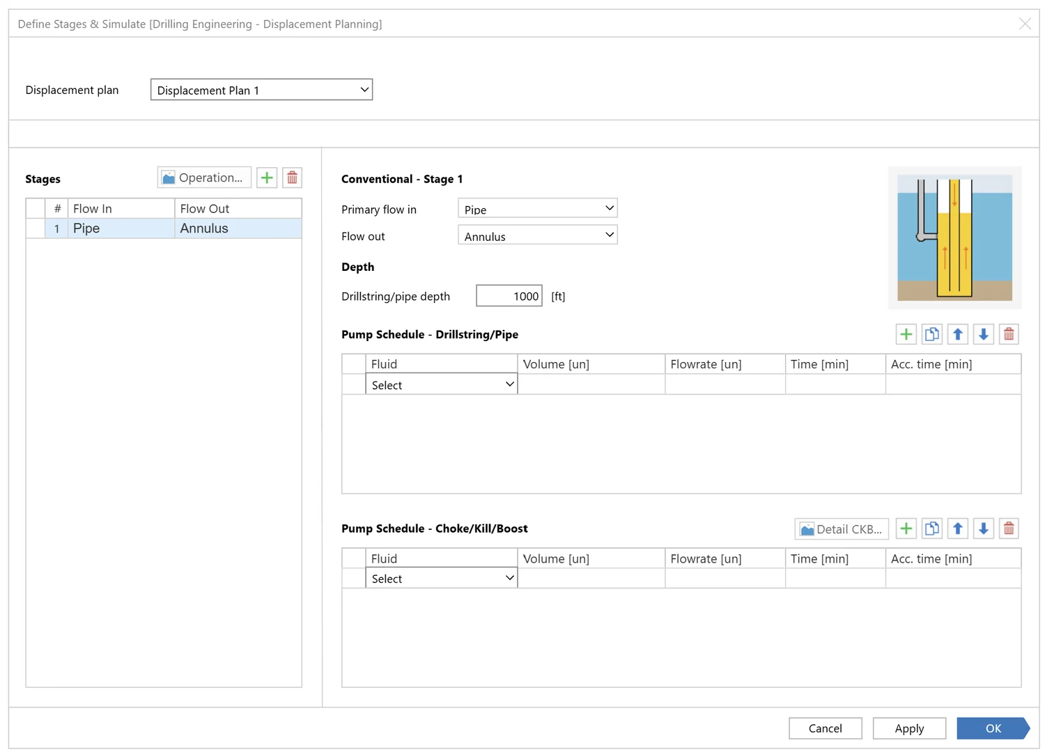
Goal
Integrate the displacement tool into JSWE and simplify complex engineering workflows without reducing functionality.
Impact
Improve usability, reduce context switching, and make displacement operations easier to learn and execute.
Success metric
Reduce configuration effort, improve workflow completion efficiency, and increase user confidence in interpreting results.
Context and outcome
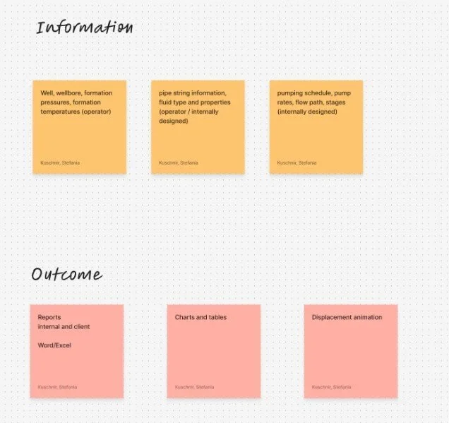
This project focused on integrating an outdated but business-critical displacement tool into a modern engineering software environment (JSWE, Jewel Suite Well Engineering). The goal was to improve usability, reduce time spent switching between tools, and make complex results easier to interpret, without compromising technical accuracy or expert control.
Fluid engineers relied on a displacement tool that was essential for their daily work, but difficult to use and disconnected from their primary software environment. By integrating this tool into JSWE, we enabled engineers to perform their complete workflow in one place, adapt faster to the new solution, and produce consistent reporting outputs for clients.
Because users were already working in JSWE, adoption was quicker, and the integration reduced cognitive load, context switching, and unnecessary repetition across tools.
The challenge
The existing displacement tool was outdated, complicated, and not designed around user workflows. Features had been added incrementally over time, resulting in:
- No clear or consistent flow
- Duplicated functionality in multiple places
- A steep learning curve for new users
- Results that were difficult to interpret without additional clarification
Even subject-matter experts were often unable to explain why certain interactions worked the way they did, which highlighted how far the tool had drifted from user-centered design practices.
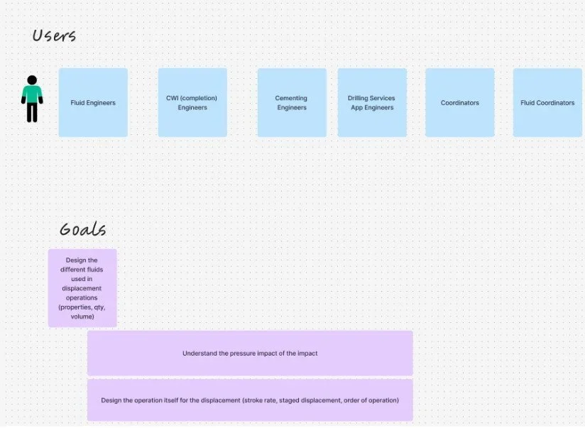
Users and needs
Primary users: Fluid engineers
Key needs:
- Faster adaptation to the tool
- A structured way to perform different displacement operations
- Reduced time spent configuring and validating setups
- Clearer interpretation of results
These users were experts in their domain, but the tool forced them to spend unnecessary effort navigating complexity rather than focusing on decision-making.
Constraints and complexity
This project came with major challenges:
- Legacy software complexity. The existing tool lacked a logical structure, had inconsistent patterns, and exposed all complexity at once, making it hard to understand and error-prone.
- Highly technical subject matter. Displacement operations involve complex fluid behavior during drilling, requiring a solid understanding of domain concepts before meaningful UX decisions could be made.
The challenge was not to simplify the domain, but to organize it in a way that supported correct and confident decision-making.
Understanding the domain
Before proposing solutions, we invested time in understanding both the domain and the legacy tool:
- SME walkthroughs explaining displacement concepts
- Hands-on exploration of the existing software
- Shared learning sessions within the UX team
This allowed us to build a baseline mental model and identify where the tool’s structure conflicted with how engineers actually reasoned about their work.
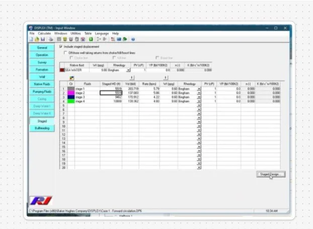
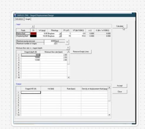
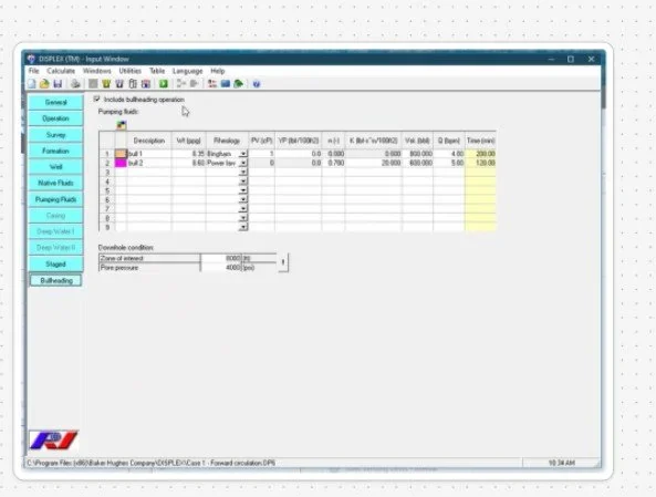
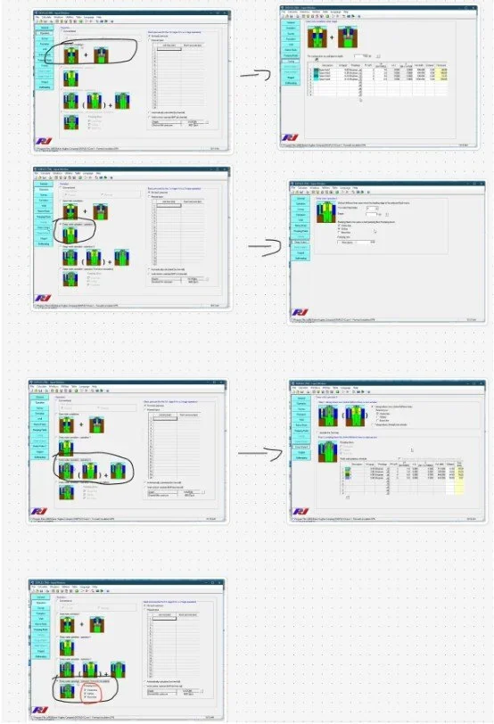
The legacy displacement tool
Reframing the workflow
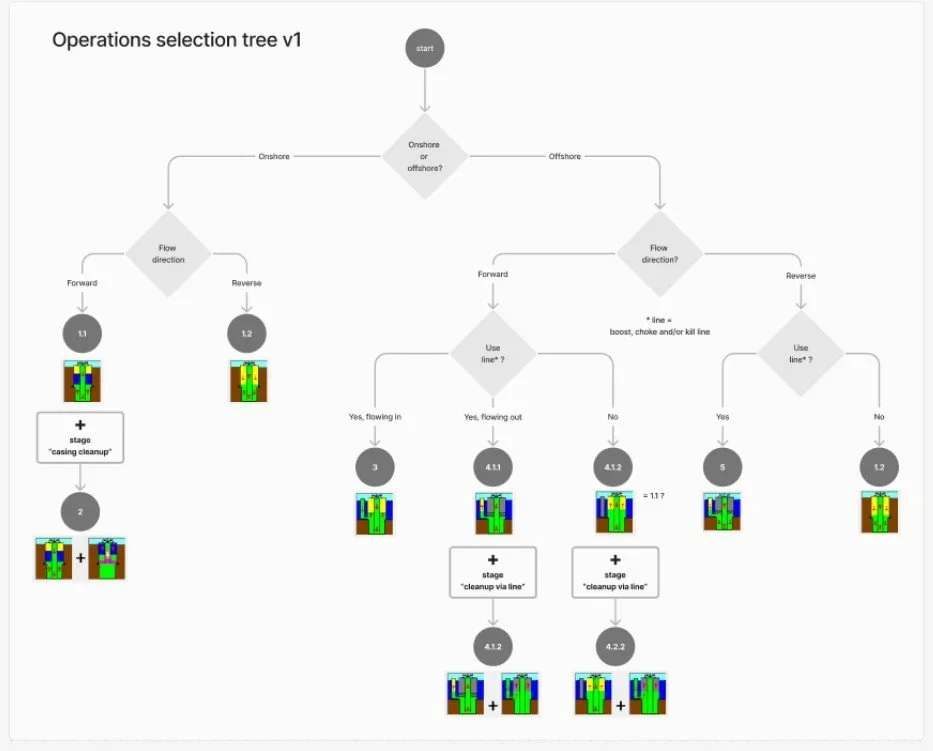
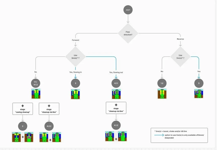
Instead of exposing all variables and configurations at once, I reframed the tool around guided decision-making.
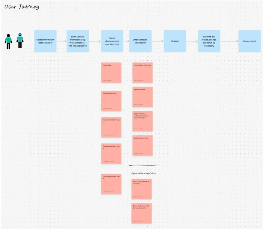
I mapped existing behavior, identified duplication and inconsistencies, and then structured the workflow into clear steps that reflected real operational logic.
Decision trees were introduced to guide engineers through valid paths, helping them focus on one meaningful choice at a time. This reduced cognitive load while preserving expert control.
UX proposals and iteration
To explore different approaches, each designer created independent UX proposals. These were reviewed internally, discussed as a team, and refined before being presented to the SME.
Feedback from the SME drove multiple iterations, ensuring that each proposal remained technically correct while becoming progressively clearer and more usable. Iteration was driven by correctness and clarity, not preference.
Wireframes and flow validation
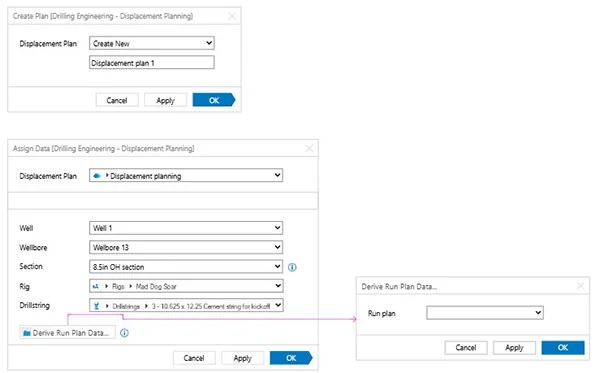
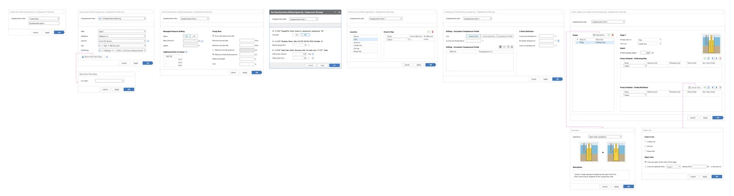
Once a direction was agreed upon, I created detailed wireframes covering:
- The full end-to-end workflow
- Each step of the displacement operation
- Supporting screens and validations
These wireframes went through several iterations and were validated with the SME to ensure that the solution combined everything the engineer needed for the operation in a single, coherent flow.
Solution overview
The final solution unified all displacement operations into one structured workflow within JSWE. Engineers could define operations, validate configurations, and interpret results without switching tools or relying on fragmented logic.
The integration reduced operational friction, improved clarity, and made the tool significantly easier to learn and use, while maintaining the technical depth required by expert users.

Visual decision support for complex operations
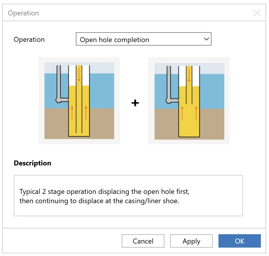
One of the most important insights from our SME was that visual representations played a critical role in operational decision-making. Engineers relied heavily on diagrams to understand displacement scenarios, validate configurations, and quickly determine the correct course of action.
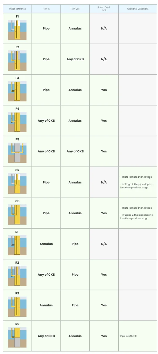
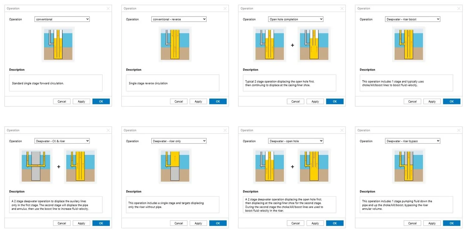
To support this workflow, I designed the final and most complex step of the process around visual guidance rather than form inputs alone. Working closely with the SME, I identified the most common displacement operations performed in daily engineering work and created a library of visual scenarios representing each operation.
To accommodate different levels of expertise and working styles, the solution supported two approaches:
Manual configuration
Engineers could build an operation step by step. As selections changed, the system dynamically updated the visual representation based on predefined rules that linked specific configurations to the appropriate diagram.
Operation templates
Engineers could start from a library of commonly used operations, each supported by clear descriptions and visual examples. Many operations consisted of multiple displacement stages, so these were shown as a sequence of steps in a table where users could review, modify, and customize the workflow.
This was a game changer
By making operational intent visible throughout the configuration process, the solution transformed a complex setup into a more intuitive and guided experience.
Engineers could reach correct configurations faster, spend less time validating assumptions, and reduce the likelihood of errors. This was particularly important because incorrect displacement configurations can lead to costly operational issues, making accuracy and confidence just as critical as efficiency.
The result was a workflow that improved speed, reduced cognitive load, minimized costly mistakes, and helped engineers make informed decisions without sacrificing the flexibility required by expert users.
Key decisions and trade-offs
Guidance vs. flexibility
Certain paths were intentionally constrained to prevent invalid configurations. This reduced flexibility but improved safety, speed, and confidence in results.
Structure vs. exposure
Instead of exposing all variables at once, the workflow progressively revealed complexity. This improved usability without hiding important information.
These decisions prioritized correctness and trust over maximum freedom.
Reflection
This project reinforced that designing for expert users is not about hiding complexity, but about structuring it. The most impactful UX improvements came from aligning the system with how engineers actually think and work, rather than how the legacy tool had evolved over time.